My english
translation perhaps it is not so good to understand the text well, for
that reason in a temporary way I will leave close the original
paragraphs in Spanish to check.
Quiero dedicar este pequeño y modesto "inventito" a don Alberto Silva - "Uranito" (LU 1DZ), quien me ha honrado con su franca amistad y sobre todo su siempre estimulante y alentadora confianza. MRG.
I want dedicate this small and modest "invention" to don Alberto Silva - "Uranito" (LU 1DZ) who has honored me with their frank friendship and mainly its always stimulant and encouraging trust. MRG.
El choke balun ha representado una solución más efectiva, desde el punto de vista eléctrico, para antenas monobanda (no estrictamente), pues no padece de los problemas de saturación, deformación, generación de armónicos, destrucción por errores, calentamiento-pérdidas, etc. de los balunes de banda ancha realizados con nucleos de ferrite.
The balun choke has given us a more effective solution, from the electric point of view, for monoband antennas (not strictly), because it doesn't suffer of aturation problems, deformation, harmonic generation, destruction due to operation errors, heating-losses, etc. of the wide band baluns made it with ferrite cores.
An unjust fame that usually attributes to balun choke is its weight. In my opinion it is not justified. The objection doesn't resist so much analysis, because if the antenna was a few meters higher would also have that additional weight due to its own additional transmission line length and its owner would not complain about it, on the contrary, it would exhibit it with pride before his colleagues.
It has devised a variant to build an excellent monoband balun based on similar principle. Substituting the usual choke winding for a parallel resonant circuit offering much higher impedance to circulating current on the external side of coaxial feeder.
En efecto, si se arrollan unas pocas espiras de cable coaxil (bastante menos que en el choke balun, desde ya) y entre los extremos de esta bobina formada con el mismo cable coaxil se suelda sobre la malla el capacitor de sintonía, como se muestra en la figura (la zona oscura del dibujo representa la malla), este conjunto bloqueará el paso de la corriente comportándose, al igual que su predecesor, como un un balun de corriente cumpliendo mejor su rol que el convencional de tensión construido con bobinado trifilar y núcleo ferrimagnético.
Indeed, if you wrap some few turns of coaxial cable (less than in the choke balun, of course) and, at the ends of this coil formed with the same cable coaxial, it is welded on the braid a tuning capacitor, like it is shown in the figure (the dark area of the drawing represents the braid), this parallel trap will block outer currents behaving, the same as its predecessor working as a current balun doing its job better that the conventional of voltage baluns built with trifilar winding and ferrimagnetic cores.
 Así, no
solamente disminuye el peso sino que la impedancia que bloquea la
corriente es mucho más elevada; únicamente un choke balun con espiras
suficientes para autorresonar con su propia capacidad distribuida
presenta la misma propiedad, pero precisa mayor cantidad de coaxil (ver
tablas de referencia
la referencia al sitio de K1TTT al final).
Así, no
solamente disminuye el peso sino que la impedancia que bloquea la
corriente es mucho más elevada; únicamente un choke balun con espiras
suficientes para autorresonar con su propia capacidad distribuida
presenta la misma propiedad, pero precisa mayor cantidad de coaxil (ver
tablas de referencia
la referencia al sitio de K1TTT al final).
No hemos visto esta solución en la literatura, no descartamos que haya sido planteada con anterioridad, si no es así nos reservamos el
copyright ;>)
In this way not
only the weight is lower, its impedance is much higher; only a choke
balun with enough turns for auto-resonate with its own distributed
capacity gives the same result, but needs more length of coaxial (see
the reference tables in K1TTT website cited at the end of this article).
I have not seen this solution in the literature, I don't discard that it
has been outlined previously, if it is not so I reserve for me the
copyright... ;>)
Alguien podría preguntarse qué sucede fuera del punto de sintonía. Dependerá de cuánta sea la desintonía. Si operamos no demasiado debajo de su frecuencia de resonancia, presentara una reactancia inductiva muy elevada, por lo cual conserva su propiedad de bloqueo. Si operamos no demasiado encima de la misma, la reactancia será capacitiva, pero también elevada, por lo cual la propiedad sigue manteniéndose. Dependerá parcialmente de la relación L/C de la trampa.
Somene could wonder what it happens outside of the resonant point. It will depend of how much the off-resonance is. If it we not operate too much under its resonant frequency, it presents a very high inductive reactance, reason why it conserves its blocking property. If we not operate too much above the same one, the reactance will be capacitive, but also high, reason why the trap, continues making its job. It will depend partially on the L/C relationship of the trap .
|
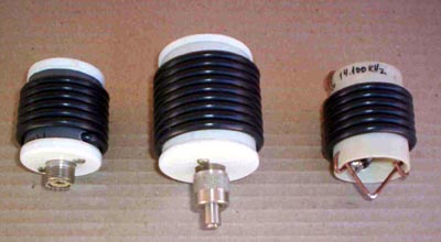
Pictures of some traps made by Hugo Martínez (LU 9DR) |
|
 |
 |
|
Three constructive variants |
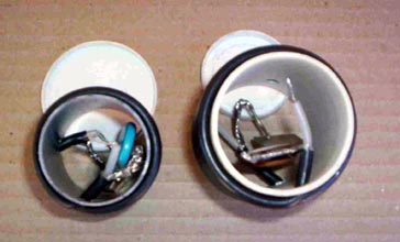
Internal sights. You can see tuning capacitors inside. |
Generalidades acerca de las trampas
(Lo que sigue es válido para trampas de antenas en general).
Para que la trampa sea efectiva, es
necesario que su impedancia sea mucho mayor que la existente en el extremo
de la rama del dipolo que se forma con esta interesante configuración. La
impedancia en ese punto del dipolo es muy elevada, fácilmente puede alcanzar
los 5000 ohms o más. Para que la trampa sea tal, su impedancia en frecuencias
cercanas a la de resonancia ha de ser de cuatro a diez veces mayor, esto
significa valores superiores a los 20000 ohms o mejor.
La impedancia a resonancia depende del Q de la bobina y el capacitor y
también de la relación L/C. Una relación L/C elevada produce a igual Q más
impedancia que una L/C más baja. Comparando las curvas se ve claramente:
Generalities about the traps
(Valid for antenna traps in general).
So that the trap be effective, it is
necessary that its impedance be much bigger that the impedance on the end of
the dipole arm formed with this interesting setup. The impedance in
that point of the dipole is very high, easily it can reach 5000 ohms or
more. So that for the trap behaves as, its impedance in frequencies near to
resonance must be from four to ten times higher, this means as high as 20000
ohms or better.
The resonance impedance depends on the coil and capacitor Q and also of the
L/C. A high L/C relationship, to same Q, gives higher impedance than a lower
L/C relationship. Comparing the curves below you can see it clearly:
La curva roja corresponde al módulo de la impedancia de una trampa formada por un inductor de 1 mH en paralelo con un capacitor de unos 125 pF. El Q de la bobina es 100, por lo tanto su resistencia equivalente paralelo está en el orden de los 8900 ohms, que es el valor mostrado en el recuadro amarillo (la imprecisión es por la dificultad de colocar el cursor en el punto exacto).
The red curve corresponds to impedance modulus of a trap built with an 1 mH inductor in parallel with a 125 pF capacitor. Coil's Q is 100, therefore its parallel equivalent resistance is in the order of the 8900 ohms; that is the value shown in the yellow square (imprecision is due to the difficulty of placing the cursor of application program in the exact point of the curve).
La curva azul representa la impedancia de una trampa compuesta por un
inductor de 20 uH en paralelo con unos 6,3 pF, también con un Q de 100, lo
cual representa una resistencia equivalente paralelo de unos 177000 ohms.
Vemos que con este par de valores la trampa es más eficaz para interrumpir
el circuito, pero en el extremo inferior de la banda (no se muestra) cae a
unos 50000 ohms. Una trampa formada con un inductor de 5 uH en paralelo con
unos 25 pF podría funcionar.
The blue curve represents the impedance of a trap made with a 20 mH inductor in parallel with 6,3 pF, also with Q=100, that give us a parallel equivalent resistance of about 177000 ohms. We see with this couple of values the trap is more effective to interrupt the circuit, but in the lower end of the band (not shown) it falls to about 50000 ohms. A trap formed with an inductor of 5 mH in parallel with about 25 pF could work better.
Nótese que la curva roja aunque tiene menor Z es muy plana y amplia (poco
selectiva), esa trampa se prestará mejor para otras aplicaciones (como
veremos en un próximo artículo sobre una trampa balun).
Notice that the red curve although it has got smaller Z it is very plane and wide (not very selective), that trap will be better for other applications (like it can see in my article: "The trap Balun").
